
Team
Buggy
Competition
Sponsors
Introduction

We came up with a few different riding positions (sitting, lying face down, front and back, side by side), but we still opted for the upright sitting position with the legs pointing forward with one rider behind the other. For size constraints, comfort, and efficiency, we feel that this position is the best.
We have decided to stick with pedaling as our mode of transferring human power to the machine (as opposed to stepping and hand cranks) because one, pedaling has been proven to be an efficient way of harnessing human power and two, bicycle parts are built for the specific purpose and are widely available.
Design Notes
A big problem with last years design is that the chain would frequently fall off the gears. But at the same time, we still want to have multiple gears to optimize our power output. This led us to the idea of an internal hub shifter. Shimano makes these hubs that have seven internal gears ($159.00 retail). This is ideal for us because we will not have to worry about different chain lengths (as is the case with mountain bike type shifters), and chain line (which leads to the high chance of the chain falling off). With this design, we will be able to run set length chains that are always taut and at the same tension. This lowers the risk of the chain falling off, as does removing the system of chain moving from sprocket to sprocket. An added benefit to this system is that we can shift without having to pedal. Furthermore, the chains that are used in conventional mountain bikes are actually designed to fall off. They are manufactured with small grooves in the chain to be easy to slide from gear to gear on the sprocket. By using the internal hub shifter, we can use BMX chains which don't have these modifications and will be less likely to slip from the sprocket.
With this in mind, we designed a system that consists of a two-stage chain connecting the pedals to the differential. The first stage of the drive system includes a fork like protrusion from the frame that will hold the crank, bottom bracket, bottom bracket shell, pedals, and chainring. All these parts are available (except the fork like protrusion which we will build ourselves) for about $150. We will be using a mix of tandem bike and mountain bike parts. A chain will run from the chainring to the internal hub shifter which is mounted in specially made slots on the frame. The internal hub shifter has an adapter mounted around it's body that allows the attachment of a second sprocket. A second chain runs from this sprocket to the differential which hangs off an aluminum plate bolted to the top of the frame.
Note also that the use of a two stage chain allows the crank protrusion to be folded about the axis of the internal hub shifter without altering the chain length.
Gearing
The gearing of the buggy is an important part of the drive train system. It allows us to optimize the speed of the buggy for a given rider strength and a given terrain. Ideally, we want the riders to pedal at a constant rate of ninety revolutions per minute regardless of terrain and speed. As we saw at the racecourse, sometimes we needed more torque (such as through the grass and sand area) and sometimes we needed more speed (such as the straight-away and downhill sections). To accomplish the different demands and yet keep the pedal rate constant, we used Shimano's internally geared hubs. However, simply using this hub does not finish the task. We still need to determine the correct gearing ratios to correspond to the correct speeds.
Design Notes
Each drive train system (front and rear) consists of three chain rings (one at the cranks, one at the internally geared hub, and one at the inner drive shaft) and one hub sprocket (see figure 1). Determining the sizes of these chain rings was simply only a matter of mixing and matching the combinations to our purposes and specifications. These include preset sprocket, speed, and space. Our internal hub shifter came with a predetermined sprocket of twenty-one teeth. We estimated the buggy to travel at an average speed of fifteen miles per hour and we wanted the rider to pedal at ninety revolutions per minute. Finally, we had restrictions on how much space was available in the frame to house the gears. With these considerations in mind, we calculated sizes of the gears.
Given:
Buggy speed: ......... 15 mph
Crank speed: .......... 90 rpm
Wheel diameter: ..... 26 inch
Find:
Chain ring sizes
>> let chainring size at crank be 34 teeth
>> let chainring size at internal geared hub be 34 teeth
(where X is the number of teeth on the chain ring on the drive shaft)
In the calculations, we estimated and set the chain ring at the cranks and the chain ring at the hub to be thirty-four teeth. From these parameters, we calculated that the chain ring at the drive shaft should have twenty-six teeth.
We did end up using all the sizes determined in the calculations except for the chain ring at the cranks. It turned out that the buggy travels at a much slower speed than predicted and therefore needed a much lower gearing ratio than calculated. Consequently, we used a twenty-four teeth chain ring at the cranks instead of the thirty-four teeth chain ring.
Fabrication Notes
We did not make the chain rings; we just bought them. However, we did have to make attachments for the chain rings to go on the internally geared hub and to go on the drive shaft. The attachments for the hub were made using a rotary table on a mill and the attachments for the drive axle was made on a lathe. Both types of attachments were not easy to make and required some careful machining. However, we can't really think of an easier way to do each piece.
We also made plates to hold up the drive shaft. These plates are slotted to allow fore/aft adjustment of the drive shaft, which in effect, allowed us to adjust the tension of one of the chains. Originally, we designed the plate to be made out of carbon fiber. However, we found out later that the plates couldn't withstand the pinching of the bolts (to hold the plate from sliding forward during pedaling), and used aluminum plates instead.
Installation of the entire system was very troublesome. Most of the difficulty came for the cramped nature of the system. There was very little space outside of the space allotted for the parts. As a result of this tight packing, we had trouble getting out hands and tools into the area to install the parts. One of the difficulties was that we could not turn the nuts holding down the hub. The hub supports just didn't allow any tools to reach in to turn the nuts. The other difficulty was installing the chain that went around the hub and the drive axle. Because the chain was at a set length (no bike derailleur system), it was very difficult pull the chain over the chain rings. Once installed however, it was also very difficult for it to come off.
Performance / Lessons Learned
The gearing system did not work well at the competition. The first problem was that the gearing ratio was still too high, even with the twenty-four teeth chain ring at the cranks. As a result, the riders stayed almost exclusively in gear one throughout the race. To fix this problem, we can either reduce the size of the chain ring at the cranks or the chain ring at the hub, or we can increase the size of the sprocket at the hub or chain ring at the drive shaft. Reducing the size of the chain ring at the cranks is simple. Unfortunately, the smallest chain ring size I know of is twenty teeth. This is some improvement over the twenty-four teeth chain ring, but not enough. Due to space restrictions on the front buggy, we can not make the chain ring on the drive shaft any larger. If the chain ring were any larger, it would run into the suspension or the chain ring on the hub. However, we do not have this problem for the rear drive shaft. After the competition we did swap out the twenty-six teeth chain ring for a thirty teeth one. The sprocket on the hub can be swapped out for a bigger one, but the biggest sprocket Shimano makes for this hub has twenty-two teeth. Again, this is not enough improvement. This leaves one final option, reducing the chain ring on the hub. At first, we thought the smallest chain ring we could use is the thirty-four teeth one because it had to be big enough to fit over the spoke flanges. However, we now believe that we can shave down the outer diameter of the spoke flanges. With a smaller outer diameter, we can construct a new attachment and use a smaller chain ring. The second problem was that the shifting mechanism for the front hub broke! The hub supports were poorly designed and constructed. As a result, the hub and the hub-shifting device were free to rotate. With the unexpected rotating motion and the hard efforts of the rider, a smaller metal ring that transmit the cable pull to gear shifting broke. Consequently, the hub was stuck permanently on first gear. To fix this problem, I strongly recommend redesigning the hub supports. After the competition, we found a .pdf order form that can be used to special order replacement parts for the Nexus internal hub shifter. This document can be downloaded here.
Constructing the chain ring attachments was pretty straightforward. Brad's only recommendation is that we use attachment plates with two types of bolt circle on them so that we could have more flexibility when swapping chain rings. This isn't possible with the current design, but we believe it can be done on future designs.
The aluminum plates we used during the competition were not well made and too thin and flexible. As a result, the pillow blocks would bind and lock the drive shaft whenever the chain pulled too hard on the drive shaft. At the competition, we made temporary solutions to hold the pillow blocks in place, but after coming back, we rebuilt the aluminum plates using thicker aluminum. Although the thicker aluminum plates work well, I think these plates are too thick and can be thinner to save some weight. I recommend doing some analysis on these plates for next year.
Although the gearing system did not work well, I believe it is still a good concept and design. If implemented correctly, this design should provide a functional, efficient, reliable gearing system. The biggest advantage of the system is that we would have a relatively simple geared system for different speeds while not having to worry about the chain falling off.
Differential
The roller clutch was one of the key components of our drive train because it was essential for the buggy to obtain true four-wheel drive. In most full-time four-wheel drive vehicles, a differential has to be used on each axle. The problem with using a differential is that if total traction is lost in any one wheel, all the torque will be delivered to that wheel and the vehicle will be immobilized. Since parts of the course consisted of sand and loose dirt, we feared loosing traction and decided against having a conventional differential. One possible solution to the traction control problem was to use a differential with a locking mechanism. Some trucks and ATV's use a lever or switch to lock the differential gears together. This basically allows the driver to turn the differential on during normal diving and off during off-road or winter weather driving. However we decided against this because it would have been hard to install and implement, expensive, and it would give the drivers another thing to worry about during the race.
 The solution to the four-wheel drive problem was suggested by our advisor when
he recommended that we use roller clutches. A roller clutch allows torque to be
transmitted in one direction and allows the other direction to rotate freely.
Most rear bicycle wheels use a ratchet, which performs a similar function as the
roller clutch. Similar to a bike, a roller clutch allows the wheels to rotate
faster than the drive shaft. This would allow the buggy to free wheel(move
without any pedaling), and allow for smooth turning.
The solution to the four-wheel drive problem was suggested by our advisor when
he recommended that we use roller clutches. A roller clutch allows torque to be
transmitted in one direction and allows the other direction to rotate freely.
Most rear bicycle wheels use a ratchet, which performs a similar function as the
roller clutch. Similar to a bike, a roller clutch allows the wheels to rotate
faster than the drive shaft. This would allow the buggy to free wheel(move
without any pedaling), and allow for smooth turning.
The reason vehicles need a differential is for turning. During a turn, the inner and outer wheels have to travel differing distances due to the fact that each wheel lies on a different radius. Without a differential, the wheels would have to slip during a turn and the vehicle would receive extreme tire wear and damage to the drive train. The roller clutch however solves this problem by allowing the outer wheel to overrun the drive axle and increase its speed around the turn.
To implement the roller clutch in our drive train we split the drive axle into an outer and inner shaft. The roller bearings were pressed-fit into the outer shaft and the inner shaft fit into the inner diameter of the roller clutch bearings. The roller clutch bearings were aligned in the outer shaft in a way to allow the outer shaft to rotate forward freely if the inner shaft were held in place. Thus when a torque is applied to the inner shaft via a sprocket mounted on the center of the shaft, the bearing's rollers would lock and the inner shaft would drive the outer shafts. The diagram below shows the set up of the system.
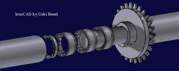
Note that three roller clutch bearings were place side by side on each outer shaft. This was done because the torque required was more than the manufacturer, Torrington, specified for one bearing. The Torrington representative also informed us that two bearings placed side by side would increase the torque the system can handle. However the max torque of the system does not increase linearly with each extra roller clutch because one of the roller clutches typically handles significantly more torque. Because we had a large supply and we were not sure if two would be enough, we decided to go with three roller clutches side by side. Two radial bearings were also used on each outer shaft. This was done because the roller clutch bearings are not designed to handle any radial loads.
Fabrication Notes
Fabricating the roller clutch system was quite difficult because of the precision required. Both the inner diameter of the outer shafts and the outer diameter of the inner shaft had to be machined to within one thousands of an inch for the system to work properly. Machining the inner diameter of the outer shaft proved to be very difficult because the inner diameter had to be bored out. The boring bars in the shop were small and would deflect when attempting to bore the chromoly steel outer shaft. The only way around this problem was to only take off a very small amount of material with each pass. Another thing to consider is that the roller clutch was designed for metric shafts but we were not able to find metric stock and thus had to do more machining on the stock. So spending some time to find a manufacturer who makes metric stock might save a lot of machining time and give the required tolerances required without any fabrication.
Performance
The roller clutch system worked extremely well on the moon buggy. The roller clutch provided our team with the only true four-wheel drive vehicle at the competition. It powered the vehicle through the sand obstacles, grass, and lunar surface obstacles. The vehicle was also able to free wheel and turn as expected.
Lessons Learned
The members of this team definitely recommend using a roller clutch differential for future teams here at Cornell, however some changes could be made to the system. One area for future teams to look into is implementing the roller clutch directly into the wheel or hub. This could illuminate weight and most importantly friction from the drive train. In our system all the u-joints, CV-joints, and half shafts continued to spin as the wheels freewheeled. If the roller clutch bearings were placed at the wheel hub then the wheel could spin independent of the rest of the drive train. One reason we did not implement this system was that we needed to place three bearings side by side plus two radial bearings in order to handle the torque required and we felt we did not have enough room in the hub for this. Future team members might want to conduct a test to determine how much torque each roller clutch transmits. Hopefully, with this information they can determine if two or three roller clutches are required. They also should look into using roller clutches' with integrated needle bearings to eliminate the need for the two outside additional bearings. This would not solve the problem of fitting the bearing assembly in a smaller space, but might significantly help it. Nevertheless we highly recommend spending some time researching ways to place the roller bearings outside of the other drive.
Half Shafts
The purpose of the half shaft is to transfer the torque from the outer shaft to the wheel hub. The half shafts were designed to be tubular with an inner diameter of 1.25". This inner diameter was set at 1.25" so that the U-joints that we bought(OD 1.25") could fit inside the tube. The half shafts were composed of chromoly steel with an outer diameter of 1.625". The outer diameter of the half shaft was determined using very conservative stress calculations, and thus the shaft was probably stronger than necessary. To save weight, the current half shafts can be turned down if future teams wish to do so. The analysis below indicates the minimum outer diameter allowed given the input parameters of the system. However, the ends of the shaft contain increased stress concentrations caused by the milled slots at the U-joints, and therefore any reduction of cross sectional area should only be performed in the center of the half shaft, away from these stress concentrations.
- Max Shear Stress = (Torque * radius) / J
- Torquehalfshaft = Torquecrank / gear ratio
- Original gear ratio ranges from 1.33 - 3.271
- Torquecrank = 1800 in lbs >> This is the maximum torque a person can apply at the crank
- Max Torquehalfshaft = 1800 in lbs >> The current gear ratio is too high, and we plan on reducing it. A ratio of 1:1 will be used in this calculation.
- Yield stress for chromoly steel = 75000 psi
- Max shear stress for chromoly steel = 75000 / 2 psi
- Max shear stress with infinite life for chromoly steel = 75000 / 4
- Factor of safety = 2
- Inner diameter of shaft = 1.25
Using these parameters the outer diameter can be calculated:
0 = C1*(OD)4 - 2.4414*C1 - (OD)
Where C1= 75000 * Gear ratio * pi / (1800*8*16) = 1.02265
OD = 1.3968"
So the middle section of the half shaft can be reduced to this value.
At each end of the half shaft there was either a CV-joint or a U-joint. The U-joints used fit snuggly inside the inner diameter of the half shaft. The outboard U-joints for the rear drive train were connected to the half shafts via a bolt that went through the shaft and then through a U-joint that sat inside of the shaft. The CV-joints in the front drive train was welded to the half shafts.
Because of both steering and suspension movements the distance between the upright and the outer shaft was not constant. Therefore the half shafts had to be able to change its effective length to account for this. So the inboard U-joints were constructed with a rod welded through it, and slots were cut into the half shaft. This allowed the welded rod to slide up and down inside the slot in the half shaft. Thus the length of the shaft was able to change while torque was transmitted to the wheels.
Fabrication Notes
Fabricating the half shafts was not easy. The biggest problem was aligning all the holes in the U-joints with those in the shaft. The easiest way to fix this problem would be to use test indicators when setting up the machining process. Unfortunately the test indicators required is not available in the fabrication lab that we use. After a lot of time spent trying to fix poorly aligned holes, all the half shafts were installed on the buggy. The right front half shaft, however, was made too short and a shim had to be created to try to fix the problem. After the competition that half shaft was scraped and a new one was built.
Performance / Lessons Learned
During the competition, the half shafts encountered no problems and worked perfectly.
Stub Axles
To transmit the power from the half-shafts to the actual wheel, we decided to use a removable connection rather than just welding the wheel to the axle. It is beneficial to be able to remove the wheel because unexpected circumstances may arise, such as a broken wheel, or a need to transport when a large vehicle is not available. If the wheels were welded to the axle, these circumstances would require that the welds be ground off before anything can be done. We looked at R/C cars and decided to copy their method of power transference because it was simple and looked effective.
 This consisted of a transfer disc that has 6 holes
around the center that line up exactly with 6 disc brake mounting holes on the
wheel. The transfer disc also has a hole in the center, matching the stub axle
diameter. We drilled a hole through the stub axle and pressed in a 3/16" x 1"
dowel pin. The transfer disc has a slot matching the location and size of the
dowel pin milled out of one face. When the transfer disc is put on the stub axle,
the pin will fit into the slot milled out of the transfer disc, forcing the
transfer disc to turn with the stub axle. The 6 holes in the wheel hub are
threaded with M-6 x 0.8 pitch threads. To create the pins needed to connect the
transfer disc and the wheel hub, we purchased a meter of M-6 x 0.8 threaded rod
and cut it up into 1" lengths, 6 for each wheel. We then removed the threads
from half of each pin. Now the pins could be threaded into the wheel hub and the
protruding bit would present a thread-less stub that would fit into the holes
drilled in the transfer disc. The end of the stub axle is tapped. After the wheel
is slid onto the stub axle and the pins are pressed into the holes in the transfer
disc, a bolt and washer is used to tighten the wheel onto the axle.
This consisted of a transfer disc that has 6 holes
around the center that line up exactly with 6 disc brake mounting holes on the
wheel. The transfer disc also has a hole in the center, matching the stub axle
diameter. We drilled a hole through the stub axle and pressed in a 3/16" x 1"
dowel pin. The transfer disc has a slot matching the location and size of the
dowel pin milled out of one face. When the transfer disc is put on the stub axle,
the pin will fit into the slot milled out of the transfer disc, forcing the
transfer disc to turn with the stub axle. The 6 holes in the wheel hub are
threaded with M-6 x 0.8 pitch threads. To create the pins needed to connect the
transfer disc and the wheel hub, we purchased a meter of M-6 x 0.8 threaded rod
and cut it up into 1" lengths, 6 for each wheel. We then removed the threads
from half of each pin. Now the pins could be threaded into the wheel hub and the
protruding bit would present a thread-less stub that would fit into the holes
drilled in the transfer disc. The end of the stub axle is tapped. After the wheel
is slid onto the stub axle and the pins are pressed into the holes in the transfer
disc, a bolt and washer is used to tighten the wheel onto the axle.
The half-shaft connected to either a U-joint or a CV-joint. The end of the joint that attached to the stub axle had two perpendicular holes drilled through it, 90 degrees apart, for 3/16"dia 1-1/4"long steel dowel pins. The 5/8" stub axle has the same two holes drilled though it, so that when the stub axle was inserted into the CV/U-joint, the holes will line up. Pins were pressed into the holes to keep the assembly together and to transfer the torque from the half-shafts to the stub axle. See Appendix B for calculations ***where is Appendix B?***
Performance / Lessons Learned
The wheels were difficlut to attach to the buggy. This is not a significant problem because they need to be removed fairly infrequently, however, if they were easier to put on and take off, it would make maneuvering the buggy in and out of doors much easier.
The slots milled into the transfer discs were cut too deep. This is very aparent on the left rear wheel where side loading on the wheel bulged out the back side of the disc. In theory, this small amount of material supports all of the side loading on the wheel, however in practice, friction between the wheel hub and the stub axle probably takes much of the load.
While doing some maintenance after the race, we removed the entire stub axle assembly and noticed that one of the two pins that attach the CV-joint to the stub axle had broken during the race. We are not sure how this could happen, because that area had two pins, while the transfer disc only had one pin.
Wheels
Originally, we planned to make our own wheels. We felt that conventional bicycle wheels would not be able to handle the side loadings they would experience. So to handle the problem, we would make our own hub and use mountain bike rims. The wide custom made hubs would be much better at handling the side loadings. However, some members of the team felt that conventional downhill specific mountain bike wheels would be good enough. After some simple tests (details of the test included later on), we decided on using conventional downhill specific wheels, namely Sun Rim's Big Fat Mammoth on Hayes disc-brake specific hub. There are a few benefits to using conventional bicycle wheels. First of all, they are already made. We just have to buy them; we don't have to spend time making them. Second, there is a wide market and many different choices to choose from. This means we can get strong quality wheels that are also light; both of which are important qualities for our buggy. Third, they come with disc-brake compatible hubs, making the integration of the braking system much simpler.
Testing
Our biggest concern regarding the strength of the wheel was how much side loading it could handle. So we performed some simple tests on well-used road bike wheels to get an estimate. To simulate the forces that would be present during the race, we supported the wheel at the axle in a horizontal position and hung weights off the rim. These perpendicular forces on the wheel would put the wheel in pure bending corresponding to the side loadings. Additional weights were added until the wheel plastically deformed. All three wheels that we tested were able to withstand about one-hundred sixty pounds each before failure. Quick estimates showed that our wheels would not experience up to one-hundred sixty pounds of side loading during the race. In addition to that, we would be getting new downhill wheels that are bigger, thicker, and therefore stronger wheels than the ones we tested.
Side Loading Calculations
Calculation #1: Side loading on wheel when buggy goes over a mogul on one side:
There were obstacles on the racecourse that would tilt one side of the buggy up about a foot. Assuming that all the weight of the buggy (four-hundred fifty lbs) is supported by the non-elevated wheels, then each wheel would be experiencing a two-hundred seventy-five lbs loading. Breaking this loading up into its components reveals that the wheel would only be experiencing about seventy lbs of side loading.
This calculation is on the high side because it does not take into account suspension and wheel camber, both of which would reduce the amount of side loading on the wheel.
Calculation #2: Side loading on wheel when buggy makes a 15 feet radius turn at 15 miles per hour.
Turning around tight corners at high speeds also creates a lot of side loading on the outside wheels.

Assuming that all four wheels share the load equally, the calculation shows that each wheel will only experience 112 lbs of side loading. This is only a rough estimate. The loads are not equally shared and wheel cambering and tire deformations will also affect the side loadings. The front outer wheel should take the most load meaning that this estimate is too low. However, deformation of the tires during the turn will soak up some of the load, and cambering of the wheels will also help reduce the side loading.
Fabrication Notes
Since we bought the wheel, there wasn't much to make. We did however have to modify the inside of the hub. We needed a shim to reduce housing size to make it fit with our hub drive shaft. Making the shim was actually quite simple. It was only a matter of time and accuracy.
Performance
The wheels worked surprisingly well despite their lightweight appearance relative to those of the competitors. I believe they worked well not only because we had well built, high quality wheels, but more importantly because our suspension system worked so well. Many teams' bulkier wheels failed at the competition.
Lessons Learned
For future buggies, I recommend performing more thorough tests to figure out exactly how much loading the wheel can withstand, or doing analysis on the current wheels to figure out how they are holding up. The wheels are critical components on the buggy and not worth risking; a failure in any of the wheels would result in automatically losing the competition.
Brakes
We used one mechanical disc brake on the rear left wheel. To implement the design, we used a disc-brake compatible wheel and mounted the disc directly to the hub. An attachment point was machined in the upright for the calipers.
Performance
The design worked well at the competition. The brake was minimally used and when used, was adequately powerful. The decision to go with Avid's mechanical disc brake as opposed to other hydraulic types was a good choice too. It is lighter and there is less hassle without the hydraulic lines. It was also cheaper.
Lessons Learned
Because our buggy is designed specifically for the competition, I believe there need no further improvements in the braking system. The design is relatively simple and easy to make; the brakes are powerful enough for the race; and we didn't run into any problems with them.
However, for riding the buggy around Cornell University, additional disc-brakes and brake levers should be installed for safety reasons. To optimize their performance, the brakes should be setup carefully to be equally powerful.